- 1. Modupe O, Kirikkaleli D (2023) Green technology, green electricity, and environmental sustainability in Western European countries. Environmental Science and Pollution Research 13: 38525-38534.
- 2. Integration of Renewable-Energy-Based Green Hydrogen into the Energy Future
- 3. Muhammad S (2013) Economic growth, energy consumption, financial development, international trade and CO2 emissions in Indonesia. Renewable and sustainable energy reviews 25: 109-121.
- 4. Adrienne O, Fetters I The causal relationship between renewable electricity generation and GDP growth: A study of energy sources. Energy economics 43: 125-139.
- 5. Stamatios N (2018) Renewable energy and economic growth: Evidence from European countries. Sustainability 10: 2626.
- 6. Isaac D, Ncwadi R, Phiri A (2021) Examining the role of climate finance in the Environmental Kuznets Curve for Sub-Sahara African countries. Cogent economics & finance 9: 1965357.
- 7. Krishna Kumar J (2022) Renewable and sustainable clean energy development and impact on social, economic, and environmental health. Energy Nexus 7: 100118.
- 8. Simona PL, Paraschiv S (2023) Contribution of renewable energy (hydro, wind, solar and biomass) to decarbonization and transformation of the electricity generation sector for sustainable development. Energy Reports 9: 535-544.
- 9. Mucahit A (2019) Renewable and non-renewable electricity consumption–economic growth nexus: evidence from OECD countries. Renewable energy 136: 599-606.
- 10. Ibrahim A (2020) A comprehensive review of recent advances in smart grids: A sustainable future with renewable energy resources. Energies 13: 6269.
- 11. Thomas JB (2012) Global energy assessment: toward a sustainable future. Cambridge University Press.
- 12. Leonardo V, Castro R (2021) Recent developments on hydrogen production technologies: state-of-the-art review with a focus on green-electrolysis. Applied Sciences 11: 11363.
- 13. Kewei H (2022) Comparative study of alkaline water electrolysis, proton exchange membrane water electrolysis and solid oxide electrolysis through multiphysics modeling. Applied Energy 312: 118788.
- 14. Xiangyu M (2022) China’s hydrogen development strategy in the context of double carbon targets. Natural Gas Industry B 9: 521-547.
- 15. Nazim MZ, Veziroğlu NT (2008) Green path from fossil-based to hydrogen economy: an overview of carbon-neutral technologies. International journal of hydrogen energy 33: 6804-6839.
- 16. Jie R (2019) Recent advances in syngas production from biomass catalytic gasification: A critical review on reactors, catalysts, catalytic mechanisms and mathematical models. Renewable and Sustainable Energy Reviews 116: 109426.
- 17. Qiao, Hui, et al. “The greenhouse effect of the agriculture-economic growth-renewable energy nexus: evidence from G20 countries.” Science of the Total Environment 671 (2019): 722-731.
- 18. Kamil K (2009) Energy and environmental issues relating to greenhouse gas emissions for sustainable development in Turkey. Renewable and Sustainable Energy Reviews 13: 253-270.
- 19. Shuxian Z (2023) Assessment of the global energy transition: Based on trade embodied energy analysis. Energy 273: 127274.
- 20. Augustine LO (2023) Global review of solar power in education: initiatives, challenges, and benefits. Engineering Science & Technology Journal 4: 209-221.
- 21. Haris I, Dincer I, Crawford C (2022) A review on hydrogen production and utilization: Challenges and opportunities. International Journal of Hydrogen Energy 62: 26238-26264.
- 22. Gaetano S, Maggio G, Nicita A (2023) The green hydrogen revolution. Renewable Energy 216: 119041.
- 23. Jeffrey JO (2023) Balancing renewable energy and river resources by moving from individual assessments of hydropower projects to energy system planning. Frontiers in Environmental Science 10: 1036653.
- 24. Richard N (2021) Global energy outlook 2021: Pathways from Paris. Resources for the Future 8: 39.
- 25. Jane BR, Jensen LE (2010) Evaluation of wind farm efficiency and wind turbine wakes at the Nysted offshore wind farm. Wind Energy 13: 573-586.
- 26. Briana N (2018) Evaluation of alternative power production efficiency metrics for offshore wind turbines and farms. Renewable Energy 128: 81-90.
- 27. Brett D, Joo HS, Kim DS (2009) Recent progress in gasification/pyrolysis technologies for biomass conversion to energy. Environmental Progress & Sustainable Energy: An Official Publication of the American Institute of Chemical Engineers 28: 47-51.
- 28. Ileana C (2022) International energy agency—iea. The Europa directory of international organizations 2022. Routledge 701-702.
- 29. Min Z, Li J (2021) A commentary of GPT-3 in MIT Technology Review 2021. Fundamental Research 1: 831-833.
- 30. Jeffrey CJ (2018) Cost-reduction roadmap for residential solar photovoltaics (pv), 2017-2030. No. NREL/TP-6A20-70748. National Renewable Energy Lab. (NREL), Golden, CO (United States).
- 31. Melanie T (2014) Future of Kenyan electricity generation: An analysis of physical and economical potential and least cost sources. MS thesis.
- 32. Klein SJW, Fox ELB (2022) A review of small hydropower performance and cost. Renewable and Sustainable Energy Reviews 169: 112898.
*Correspondence: Published Date: March 19, 2025 Citation:
Finite difference or conventional conforming finite element methods currently used for the
analysis of rotating discs do not normally provide safe lower-bound predictions of the plastic burst
speed. It is of potential concern when developing a disc geometry if later in the detailed design stage
it is found to be structurally inadequate. This paper presents the development and illustrates the
performance of an equilibrium finite element that provides safe lower-bound predictions of the plastic
burst speed irrespective of mesh refinement. The element, which is termed the Lamé Finite Element,
offers engineers a safe design methodology and, through dual analysis, the possibility to quantify the
uncertainty in the burst speed prediction.
Keywords:
Lamé Finite Element, Equilibrium Finite Element, Rotating Discs, Plastic Assessment, Burst Speed.
Introduction:
In designing the rotors of high-speed turbomachinery, the engineer is primarily concerned with
determining a disc geometry that has sufficient strength to withstand failure by bursting at the highest
foreseen over-speed condition. The failure of a rotating disc by burst is an extremely serious eventinvolving significant kinetic energy due to rotation being transferred to unconstrained disc fragments,typically a small number of disc sectors, and associated shrapnel which then act as projectiles. The
avoidance by design of disc burst is a particular issue in aeroengines where the engine casing cannot
economically be designed to constrain the post-failure projectiles.
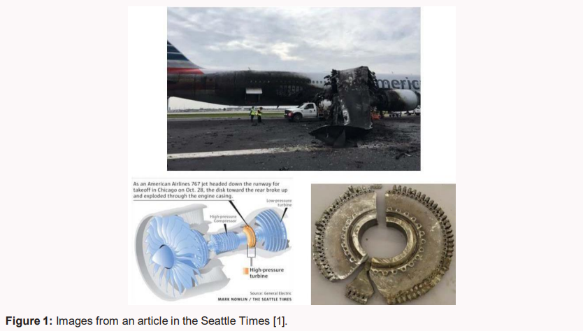
Whilst, thankfully, rare, disc burst in aeroengines has occurred in commercial aircraft, typically
during take-off when the engine is most highly loaded. In a rather clearly written article published
on 4th November 2016 in the Seattle Times, Dominic Gates details one case of a disc burst in a GE
aeroengine of a Boeing 767 as it was taking off from Chicago [1], and some of these images presented
in this article are reproduced in Figure 1.
It is essential, therefore, that the engineer has robust analysis tools capable of predicting the burst
of rotating discs of fairly arbitrary disc geometries with accuracy. It is also the case where the disc
geometry is to be established through design-by-analysis that the tool is efficient so that a range of
geometries may be considered with minimal computational effort.
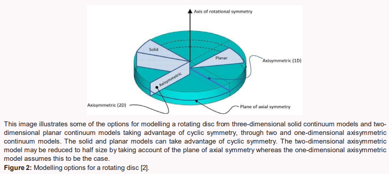
By dint of the blades, the disc should be considered as a three-dimensional cyclic-symmetric model.
It is traditional, however, to smear the loads of the blades over the entire periphery and adopt a
two-dimensional axisymmetric continuum model. A further reduction of dimensionality from two
to one is also generally acceptable where the disc exhibits symmetry about an axial plane and where
the plane-stress constitutive relations are valid, as is normally the case for rotating discs.
In this manner the disc is represented as a line of variable thickness with only the radial and hoop
stresses being considered. Such one-dimensional axisymmetric continuum models are quick to
generate and analyze and, as such, are ideal for the initial design of rotating disc geometries.
The features of the disc that are not captured accurately with such an idealization don’t significantly
influence the geometric design of the disc and can be dealt with at a later detailed design stage.
Some of the modelling options and idealizations are illustrated in Figure 2.
There exist closed-form linear-elastic theoretical solutions for the one-dimensional idealization the simplest
of which was presented by Lamé for discs with parallel sides, i.e., uniform thickness – see [3] for example.
Theoretical solutions have also been established for more complex disc geometries, e.g., tapered geometries
and the ubiquitous constant stress geometry. These have been presented in [4] and [5]. Although discs have
been designed using such solutions, geometric features such as balancing or sealing rings often mean that these
solutions cannot be used. In such cases the engineer resorts to numerical methods. In [5] the finite difference (FD)
approach is presented and it is the experience of the author, who worked in the turbomachinery industry for a
decade, that these approaches are still used.
As with all numerical methods, the FD approach produces an approximate solution whose convergent properties
are not always clearly defined. The more modern finite element (FE) method is also approximate but can be shown,
if the method is appropriately formulated, to converge to the theoretical solution with mesh refinement. For most
finite element systems, in particular the large legacy systems, the formulation adopted is based on conforming
displacements which leads, by definition, to compatible strains and is known as the conforming finite element
(CFE) formulation. The displacement shape functions are generally polynomial and are, therefore, particularly
unsuited to capturing the displacement variation in a rotating disc which, for the parallel sided disc, involves
rational terms in the radial ordinate. As such, significant mesh refinement is required for such a CFE model to
converge to the theoretical solution. The error in an unrefined CFE model manifests as a lack of equilibrium
between the applied loads and the internal stress field and tends to lead to approximations that produce unsafe
upper-bound predictions of quantities such as the burst speed. Thus, in order to achieve a result that can reliably
be used in design, the engineer needs to undertake a process of solution verification [6], which enables extrapolation
to an estimate of the theoretical solution. Unfortunately, in the majority of commercial FE systems, solution
verification is a manual process requiring not inconsiderable effort from the engineer which tends to detract from
the task in hand, i.e., the design of a structurally sound disc geometry.
Through a belief in common with his colleagues that the practicing engineer is better served using an
equilibrium finite element (EFE) formulation, the author has devoted a significant part of his career to the research,
development and application of such models. With an EFE formulation strong equilibrium is guaranteed, ensuring
that predictions of the burst speed converge from below the theoretical solution. In this manner, the solution from
even the crudest meshes is safe and the engineer can concentrate on the disc design comforted by the knowledge
that even without formal solution verification, the burst speed predicted by the model will lie on the safe side of
truth.
In this paper the Lamé solution for parallel-sides rotating discs with a plane-stress constitutive relation is
used to construct a finite element stiffness matrix and load vector. The resulting element is one where both strain/
displacement compatibility and stress/load equilibrium are satisfied exactly and, in this sense, it is a Trefftz finite
element (TFE) formulation [7]. These elements can be assembled in the usual manner to provide models that
represent the true disc geometry in a piecewise uniform fashion.
In contrast to a CFE model, which requires considerable mesh refinement to recover a reasonable approximation
to the linear-elastic solutions governed by the Lamé equations, the TFE model will recover the solution with a
single element. For this reason, the author has called this element the Lamé finite element (LFE).
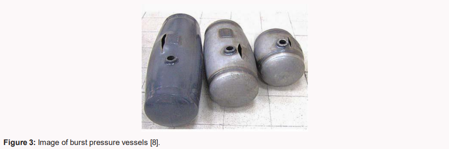
Like rotating discs, pressure vessels are another safety critical component where LFE would provide a sensible
and safe alternative to conventional methods. Pressure vessels can burst in a ferocious nature particularly when
containing compressible gases – see Figure 3 which presents an image taken from [8].
Much research has been undertaken into the advantages of pressure vessels formed of compound rings and
there are many published examples where the Lamé equations are laboriously written out for each ring and then
coupled with the appropriate continuity conditions. This approach probably comes from strength of material texts
where it is often presented as a method for such components – see for example [3]. A far tidier approach would be
to adopt a mesh of LFEs. Although not considered in this paper, the load vector for thermal body loads is simply
determined and the contact condition between adjacent rings can be handled efficiently using gap elements and an
iterative analysis. The first example shown in this paper illustrates the performance of an LFE model and compares
this to that of CFE models for a pressurized pipe or vessel.
Plasticity is considered in the examples presented in this paper. In determining the plastic limit load the
material is often idealized as an elastic, perfectly-plastic material model and this idealization will be used in this
paper. Strain-hardening could be included and would certainly be included at the detailed design stage. However,
for the initial design of disc geometry ignoring strengthening likely to be achieved through strain-hardening is
considered a reasonable conservative approach.
In modelling the plastic behavior of the disc material as the speed increases beyond that which causes first
yield, a number of numerical approaches may be adopted. As the plastic limit load or burst speed is unique then
this measure should be independent of the approach used. The common approach used in commercial FE systems
is the incremental approach [9]. Here the load is applied incrementally based on a linearized extrapolation of
the material state at the start of the iteration. After each increment an iterative approach is required to bring the
solution back onto the correct material state.
An alternative approach that exploits the strong equilibrium from EFE models is that of lower-bound limit
analysis. An example of this approach for plate elements is shown in [10]. In this approach a solution from a
linear-elastic EFE model is used as a particular solution. To this solution is added a set of self-balancing or
hyperstatic stress fields the amplitudes of which are determined in a mathematical program so as to maximize
the load factor whilst respecting the yield constraints. This approach has been successfully implemented for the
LFE model.
A third approach is the elastic compensation method (ECM) [11]. This is a very simple iterative approach that
is easily implemented in software. It is rather flexible in terms of the yield criterion adopted and has been used
to produce the plastic solutions presented in this paper. It is worth noting with regard to the material idealization
used in this paper that no strain limit has been accounted for in the solutions. The assumption made is that the
material has sufficient ductility to allow the plastic solution to fully develop. Whilst the materials used for real
discs is usually ductile, this property will have some limit and will certainly need to be formally checked at the
detailed design stage.
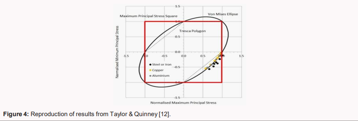
The two yield criteria generally adopted for ductile metals are the Tresca and the von Mises criteria. The work
of Taylor & Quinney [12], has demonstrated that the von Mises criterion provides a more accurate representation
of yield than the Tresca criterion – see Figure 4. The simplicity of the Tresca criterion, which is a conservative
linearization of the von Mises criterion, means that it is often used in the development of theoretical solutions – see
for example [13].
It is the case, as seen in Example 1, that even for a uniform thickness geometry where the elastic solution
is exact, mesh refinement is required to obtain an accurate prediction of the corresponding plastic solution. The
iterations required by the ECM are based on linear elastic solutions and so the solution at any stage of mesh
refinement and plastic iteration is an equilibrium solution and offers a lower-bound estimate of the burst load.
Following Example 1 a section is introduced to illustrate how the piecewise uniform thickness LFE model
provides predictable lower-bound solutions for disc geometries that are not parallel-sided but where the thickness
decreases monotonically with increasing radius. This feature is further demonstrated in Example 2 which shows
how an LFE model can accurately capture the solution for the well-known case of the uniform strength disc.
In Example 3 the analysis of a real rotor with blade loads is considered. Results from two elastic finite difference
(FD) methods have been published and the performance of an LFE model is compared with these results.
The practical advantages of the LFE method over the FD or CFE approaches means that a safe and reliable
tool could be developed for the design-by-analysis of rotating discs. An example of this technique is presented
in Example 4 where the geometry of the disc is modelled using a cubic Bezier curve. Two geometric variables
(position of the Bezier control points) are considered and design curves are produced and overlaid on a contour
plot of disc mass. Although relatively simple, this example demonstrates the relative ease with which a designby-analysis tool can be developed. It should be noted that this sort of tool could be developed into a real-time
analysis tool where the control points are moved around through user interaction with the mouse. Even though to
achieve full convergence in the earlier examples extremely refined LFE meshes have been used, with reasonable
computing power these models take only a few fractions of a second to complete.
In the discussion section consideration is given to the performance of burst predictions based on elastic rather
than plastic analysis. Criteria such as the Robinson Burst Criteria define the speed of burst as that when the average
elastic hoop stress reaches the ultimate strength of the material. This criterion gives an exact prediction for uniform
thickness discs but is approximate and unsafe for other non-uniform disc geometries. It is also the case that hoop
burst is not the only form that might occur in a rotating disc. Whereas hoop burst essentially requires the entire disc
to reach a plastic state, a form of failure called radial burst can and does occur in disc geometries where the web
between hub and rim is essentially parallel sided. The disc considered in Example 3 has the sort of geometry where
radial burst occurs. At a given radius the radial stress reaches yield which, at least for the Tresca yield criterion,
indicates failure around an annular ring of the disc. Again, the strong equilibrium achieved with an LFE model
ensures that this mode of failure is accurately captured.
Given that CFE and LFE models provide upper and lower bounds on the exact solution, the idea of dual
analysis to quantify the uncertainty in a particular solution is discussed. In this work it has been observed that the
stiffness matrix for the CFE element when using reduced integration is identical to that of the LFE element. This
means that with suitable modified post-processing of the CFE results the same solution obtained with an LFE
model can be obtained at minimal computation cost and without the necessity for reanalysis of the model.
In the final section of this paper, conclusions are drawn as to the utility of the LFE method for the practical
initial design of rotating discs and ideas for further developments are expressed.
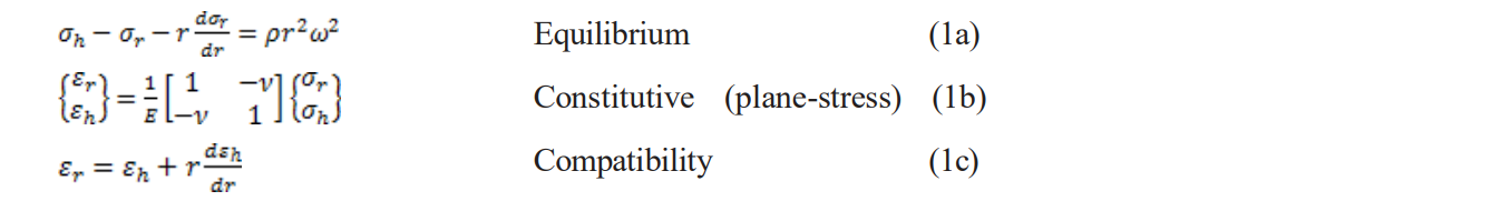
The Lamé Equations
Although a plane-strain constitutive relationship between stresses and strains may be appropriate for rotating
components with large axial thickness, e.g., a shaft, the plane-stress relation is universally considered appropriate
for rotating discs which have relatively thin axial dimensions.
Combining the three equations, Eq. (1), and recognizing the appropriate strain displacement relations leads to
the second-order differential equation given in Eq. (2), which can be solved for the radial displacement,u.
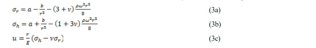
The Lamé equations, Eq. (3), give a solution to this differential equation in terms of the two Lamé coefficients,
a and b. These coefficients are determined from the boundary conditions for the problem.
For a force-driven problem, with radial boundary forces,
fi and fi,
at the inner and outer radii,
ri and ro,
the Lamé coefficient may be determined from
Eq. (4),
where E transforms boundary forces into corresponding
internal stresses and is thus termed the Equilibrium Matrix.
Whilst the matrix E is singular for an element with the inner node
on the axis of rotation, i.e., ri = 0, the inverse of this matrix,
E-1, may be written explicitly as shown in
Eq. (5).
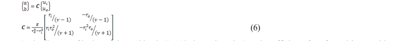
A similar expression can be written in terms of radial boundary displacements,
ui and uo,
for displacement-driven problems as shown in Eq. (6),
where C transforms boundary displacements into corresponding
internal strains and is thus termed the Compatibility Matrix.
In the absence of body and thermal loads, Eq. (4) determines the Lamé coefficients for a force driven problem
whereas Eq. (6) does so for a displacement driven problem. Whilst the vast majority of Lamé problems are force driven,
one can conceive of other problems which are displacement driven or mixed problems. It is necessary, therefore, to be able
to identify a solution of the Lamé equations that copes with the full range of possible boundary conditions, and such a general
solution can be obtained by equating Eq. (4) to Eq. (6) as shown in Eq. (7). In this manner, the Lamé coefficients
are eliminated, leading to two equations expressed in terms of the two boundary forces and displacements, which may be
solved for arbitrary boundary condition specifications.
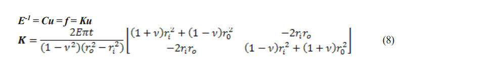
A standard stiffness formulation with the stiffness matrix
k can be derived from Eq. (7) as shown in Eq.(8) .
One of the properties of an element stiffness matrix is, according to the
Maxwell-Betti reciprocal theorem, that it should be symmetric,
and this property is seen observed for the LFE. Since there are
no rigid-body modes of displacement associated with this element, the stiffness matrix is
non-singular for ro > ri , and
could be inverted into a flexibility matrix if so desired.
Body Loading
This form of loading was neglected in the development of the stiffness equations in order to concentrate the
reader’s mind on the direct formulation presented. It is, however, simply included by adding the appropriate term
to the right-hand side of the stiffness equations. If body loading is included then the equilibrium equations of Eq.
(4) expands to the form shown in Eq. (9).
Alternatively, the compatibility formulation of the system of equations is as shown in Eq. (10)
As already shown, equating Eq. (9) and Eq. (10) eliminates the Lamé coefficients and pre-multiplying by
leads to Eq. (11) which are the stiffness equations including the full set of boundary and body loading.
The matrix E is singular when
ri = 0 but this singularity can be bypassed
by expanding the expressions in Eq. (11) symbolically
as shown in Eq. (12).
The stiffness equations for a single LFE element are assembled in the usual manner
to form the structural stiffness equations for the disc, the solution to which comprises the
nodal displacements. The nodal forces that hold each element in equilibrium
with respect to the applied loading are simply recovered using the nodal displacements in the stiffness equations
for the element, and the internal stresses and displacements can be recovered using
Eq. (3) once the
Lamé Coefficients for an element have been evaluated using either
Eq. (9) or
Eq. (10).
The radial, σr, and hoop stress, σh are principal stresses.
It is common, for the sort of ductile metals used for rotors, to adopt the von Mises yield criterion as the failure criterion.
For this yield criterion the so-called ‘equivalent stress’, sE, is given by
Eq. (13c) and the maximum principal stress and Tresca criterion which will also enter into the discussion
are expressed in Eq. (13a) and Eq. (13b) respectively.
A linear-elastic solution is only valid if the maximum value of the equivalent stress in the rotor is less than or equal to the yield stress,
SY, this usually being determined from a uniaxial tensile test.
The maximum equivalent stress,
SE,
occurs at a point termed the ‘critical’ point or radius. When discussing and plotting yield diagrams it is common to work in terms of
normalized principal and equivalent stresses. The normalization involves dividing by the yield stress and normalized quantities are indicated
with the tilde, so, for example, the normalized equivalent stress at a particular point would be
SE =
SE/SY.
The maximum normalized equivalent stress is given the symbol
SE.
An engineer designing a rotor would typically need to ensure that the maximum equivalent stress at the operating or design speed,
ωa, is below some prescribed design stress.
Note that the analysis is generally undertaken at the design speed.
At the detailed design stage, the design stress will typically be based on considerations of fatigue/creep failure and is likely to be a fraction of the yield stress for the material.
At the initial design stage, however, the disc will generally be designed based on the plastic burst speed,
ωp, which is the output of a plastic analysis.
A non-dimensional plastic load factor,
λp, may be defined as given in Eq. (14).
The elastic limit speed is often also of interest,
ωe as the speed at which first yield occurs and the corresponding
elastic load factor is defined in Eq. (15) where the manner in which
ωe is calculated based on the elastic stress is shown.
Despite the seemingly counter-intuitive idea that stress measures from an elastic analysis might be helpful in
the prediction of plastic burst, such metrics have and are still used in the early design stages of a rotating disc.
These stress metrics are shown in Eq. (16).
The predicted burst speed associated with the stress metrics given in Eq. (16) are provided in Eq. (17).
In addition to point displacements and stresses, there are some additional model metrics that are useful when it
comes to the design of rotors. Obvious candidates here are the mass and inertia of the rotor as one of these will
tend to be the objective function in a design scenario. Another useful measure is the utilization,
U. This is a measure of how well the capacity of the rotor is being used and lies in the range
0 ≤ U ≤ 1. It can be considered as a pointwise
quantity defined as SE/SY
or, perhaps more usefully, as an average value for the entire rotor as shown in Eq. (18)
where 𝔸 is the area of the rotor generatrix.
The transition to sustainable energy systems is essential to address global environmental
challenges, with green electricity production playing a crucial role. This comprehensive review
examines the advancements in green electricity production technologies, focusing on solar, wind,
biomass, and hydroelectric power. By exploring the efficiency, cost trends, adoption rates, and
environmental impacts of these technologies, the review highlights their potential to transform the
energy landscape.
Solar PV and wind energy have seen substantial improvements in efficiency and cost reduction, while biomass and hydroelectric power offer valuable contributions to a diversified
renewable energy portfolio. Despite the challenges, ongoing research and innovation are driving
the adoption and integration of these technologies, paving the way for a sustainable and resilient
energy future.
The findings underscore the importance of leveraging a multifaceted approach to green
electricity production, emphasizing the need for continued advancements and strategic integration of
renewable energy sources.
Renewable energy; Green electricity; Solar power; Wind energy; Biomass energy;
Hydroelectric power; Sustainable energy; Energy efficiency; Emerging technologies
The transition to sustainable energy systems has become imperative in addressing global
environmental challenges, with green electricity production emerging as a key component. This
comprehensive review explores the various technologies and strategies that are driving advancements
in green electricity production, highlighting their potential to transform the energy landscape.
The shift towards renewable energy sources such as wind, solar, and hydroelectric power has
gained significant momentum in recent years. These technologies are pivotal in reducing greenhouse
gas emissions and mitigating the impacts of climate change.
Advancements in biomass energy production have also contributed to the diversification of green
electricity sources. Biomass conversion technologies offer a renewable and carbon-neutral option
for generating electricity, addressing the need for sustainable energy solutions in various regions.
The economic and environmental benefits of green electricity production are well-documented.
Studies have shown that renewable energy sources such as hydropower, waste, biomass, and wind
power play a crucial role in driving economic development while minimizing environmental footprints.
In conclusion, advancing sustainable power through green electricity production requires a
multifaceted approach that leverages innovative technologies and strategic integration of renewable
energy sources. This review provides a comprehensive understanding of the path towards a
sustainable and resilient energy future.
Green electricity production has seen significant advancements, driven by the urgent need to mitigate climate
change and reduce dependency on fossil fuels. This section reviews the latest research and developments in green
electricity production technologies, focusing on green hydrogen, biomass energy, wind, solar, and hydroelectric power.
Green hydrogen production has emerged as a promising avenue for sustainable energy. Studies have
highlighted the potential of water electrolysis using renewable energy sources such as solar and wind power
to produce hydrogen without carbon emissions.
The efficiency of green energy production varies significantly across different technologies. This section
compares the efficiency of solar, wind, biomass, and hydroelectric power, highlighting their advantages and
limitations.
Solar Energy: Solar photovoltaic (PV) cells have seen substantial efficiency improvements over the years.
Modern PV cells convert sunlight into electricity with efficiencies ranging from 15% to 22%, with research cells
achieving up to 26% efficiency.
Wind Energy: Wind turbines convert kinetic energy from wind into electricity with efficiencies between 35%
and 50%. Offshore wind farms tend to have higher efficiencies due to stronger and more consistent wind speeds.
Biomass Energy: Biomass energy production efficiency depends on the conversion technology used.
Gasification and pyrolysis are commonly used methods, with efficiencies ranging from 20% to 40%.
Hydroelectric Power: Hydroelectric power is one of the most efficient forms of renewable energy, with
conversion efficiencies often exceeding 90%. Small-scale hydroelectric projects, while less efficient than large
dams, still offer significant efficiency and environmental benefits.
In conclusion, advancing sustainable power through green electricity production requires a
multifaceted approach that leverages innovative technologies and strategic integration of renewable
energy sources. This review provides a comprehensive understanding of the path towards a
sustainable and resilient energy future.
The cost of green electricity production has been declining, making it increasingly competitive with traditional
fossil fuels. This section analyzes the cost trends for solar, wind, biomass, and hydroelectric power.
Solar Energy: The cost of solar PV electricity has decreased dramatically over the past decade, with the
average cost falling from $0.37 per kWh in 2010 to $0.05 per kWh in 2020. Factors contributing to this decline
include economies of scale, technological advancements, and reduced manufacturing costs.
Wind Energy: The cost of wind energy has also seen significant reductions, particularly for onshore wind
farms. The average cost decreased from $0.09 per kWh in 2010 to $0.04 per kWh in 2020. Offshore wind energy
costs remain higher but are expected to decrease as the technology matures and deployment scales up.
Biomass Energy: Biomass energy costs vary widely depending on the feedstock and conversion technology.
The average cost ranges from $0.05 to $0.10 per kWh. While biomass energy is generally more expensive than
solar and wind, it offers the advantage of being a dispatchable source of electricity.
Hydroelectric Power: Hydroelectric power remains one of the most cost-effective renewable energy sources,
with costs ranging from $0.02 to $0.05 per kWh. Large-scale hydroelectric projects benefit from long lifespans
and low operational costs, making them highly economical over the long term.
Advancing sustainable power through green electricity production is critical for mitigating climate change
and reducing dependency on fossil fuels. This review has highlighted the significant advancements in solar, wind,
biomass, and hydroelectric power technologies, demonstrating their potential to revolutionize the energy sector.
The adoption rates of these technologies vary globally, influenced by regional resources, policies, and economic
conditions. While challenges remain, such as technological limitations, economic barriers, and policy issues, the
ongoing research and innovation are essential for overcoming these obstacles.
In conclusion, a multifaceted approach that leverages innovative technologies and strategic integration of
renewable energy sources is crucial for advancing green electricity production. By embracing these technologies,
we can significantly reduce carbon emissions, promote economic growth, and achieve global sustainability goals.
Continued research, investment, and policy support are vital to realizing the full potential of sustainable energy
systems and ensuring a resilient energy future.
A Lamé Finite Element for the Initial Design of Rotating Discs

OPEN ACCESS
Angus Ramsay, PhD, FIMechE (Director), Ramsay Maunder Associates Limited, UK
Angus Ramsay. A Lamé Finite Element for the Initial Design of Rotating Discs. Collect J Mech Eng. Vol 1 (1) 2025; ART0071

Abstract
In this section the essential steps in the derivation of the Lamé equations are stated. The complete derivation
can be found in many standard and advanced texts, for example, see [14]. The geometrical parameters involved in
the representation of a rotating disc and the boundary terms are illustrated in Figure 5.
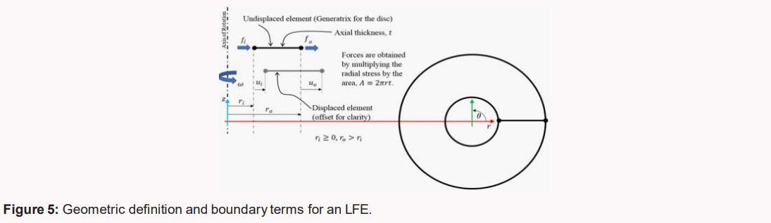 In this paper we consider a uniform thickness axisymmetric body defined in a cylindrical coordinate system,
r, θ. Boundary loading will be considered along with body loading due to a constant angular velocity,
ω. For the isotropic materials considered in this paper, the elastic properties of the material are defined by the
elastic modulus, E, and Poisson’s ratio, ν, with the mass density of the material denoted by
ρ. In the absence of torque and angular acceleration there are no shear stresses or strains and the two stress
components of interest are the radial stress, σr, and the circumferential or hoop stress,
σh, which have corresponding strains εr and
εh respectively, these then being principal values. The equations of equilibrium, constitution and
compatibility for this axisymmetric problem are given in Eq. (1).
In this paper we consider a uniform thickness axisymmetric body defined in a cylindrical coordinate system,
r, θ. Boundary loading will be considered along with body loading due to a constant angular velocity,
ω. For the isotropic materials considered in this paper, the elastic properties of the material are defined by the
elastic modulus, E, and Poisson’s ratio, ν, with the mass density of the material denoted by
ρ. In the absence of torque and angular acceleration there are no shear stresses or strains and the two stress
components of interest are the radial stress, σr, and the circumferential or hoop stress,
σh, which have corresponding strains εr and
εh respectively, these then being principal values. The equations of equilibrium, constitution and
compatibility for this axisymmetric problem are given in Eq. (1).

Development of the Element Stiffness Equations


Post-Processing & Results


Abstract
Keywords
Introduction
Conclusion
Related Work
Green Energy Production Efficiency
Conclusion
Cost Analysis
Conclusion
References